
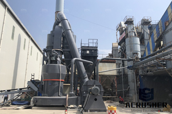
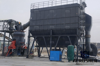
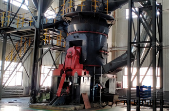
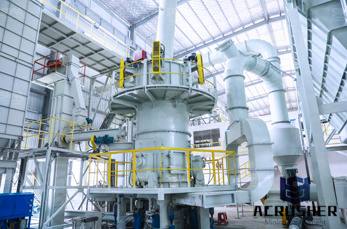
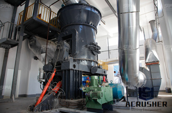
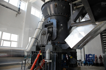
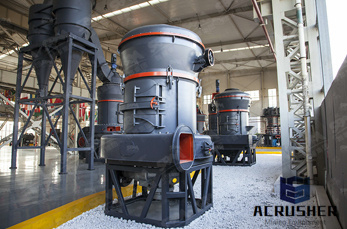
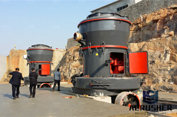
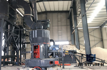
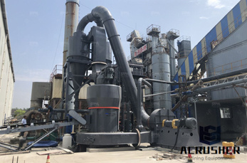
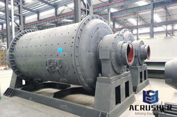
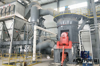
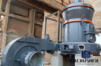
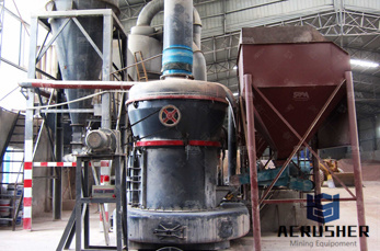
vertical mill engineering drawing method manufacturer Grasping strong production capability, advanced research strength and excellent service, Shanghai vertical mill engineering drawing method supplier create the value and bring values to all of customers.
 WhatsApp)
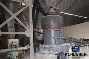
MILLING MACHINE OPERATIONS OD1644 LESSON 1/TASK 1 discussed in this text. Keep in mind that although we are discussing a knee and a column milling machine, this information can be applied to other types. Use figure 1 on page 3 (which illustrates a plain knee and column milling machine) to help become familiar with the location of the various
Sep 03, 2017· Institute of Engineering Pulchowk Campus Department of Mechanical Engineering ENGINEERING DRAWING II (ME 451) [Tutorial Sheets] 2073 1 ... The axis of the three solids lies in the same vertical line. Draw the isometric view. ... Download "Engineering Drawing II Tutorial" Kami adalah komuniti perkongsian.
require an understanding of its creator, only an understanding of engineering drawings. An engineering drawing is a means of clearly and concisely communicating all of the information necessary to transform an idea or a concept in to reality. Therefore, an engineering drawing often contains more than just a graphic representation of its subject.
A Handson Approach in Teaching Machine Design . Introduction . ... refresh their knowledge and skills in delivering an engineering drawing according to standards. ... (HAAS VF1 Vertical Milling Machine) in Figure 4 will be used to manufacture the mold. Students will be given step by step instructions to save their Gcodes in the Haas mill
Time limited offer Turn around your drawing in 48 hours, price starts from 60 per ...
Manual Vertical Mill CNC 3Axis Vertical Mill Manual Horizontal Mill Manual Turret Lathe CNC Turret Lathe ... The proposed time estimation method has the following sequence: 1. Begin with an engineering drawing 2. Develop a process plan ... plan from a part drawing. Appendix A is a detailed time estimate of a "rod
ME 111: Engineering Drawing Lecture 9 Projections on Auxiliary Planes ... The auxiliary view method may be applied To find the true length of a line. To project a line which is inclined to both HP and VP as a point. ... vertical plane and denoted as AVP.
CNC Application and Design by Patrick Collins, Charles Cummings, Wesley Dittrich, Paul Jones, Andrew Sealey ... We acquired primary machine shop skills that provided us an opportunity to mill and drill a class of components to specified dimensions and tolerances. For each component, we created a detailed engineering working drawing that helped ...
Milling and Machining Center Basics Fundamental Manufacturing Processes Video Series Study Guide 3 In all kinds of milling a critical component is the workholding device and the ability to be changed over quickly to present new work or work surfaces to the tooling. Machining centers can utilize long machine beds, pallet changers and
Milling Machine projects For Mechanical Engineers. This article contain list of projects for mechanical engineering students related to Milling Machine projects .This list contain projects which are helpful for Mechanical, Diploma Mechanical Students For Final year Submission .
It is the operation of production of a flat vertical surface on the side of a workpiece by using a side milling cutter. ... It is a method of milling by means of two or more cutters simultaneously having same or different diameters mounted on the arbor of the milling machine. ... Engineering Drawing ( Graphics)
The THORS Engineering Drawings for Machining course introduces the learner to the unique features of a machining engineering print and offers insight into the finishing processes used to manufacture the specified machined component. ... State why method of operation is a focal point on drawings and how it applies to OEMs.
Sep 23, 2014· Basic Engineering Drawing – Projection Engineers are confronted with the task of communicating the design, development and structures of machines to manufacturers and builders. The shape and size of various parts of a machine and its structure must be recorded on plane sheets in a systematic way for communication.
Isometric drawing is the most commonly used method of pictorial drawing. Isometric drawings are built on three lines, called isometric axes. One is drawn vertically and the other two with the 30° set square either side of it. An Isometric drawing is a way of presenting designs in three dimensions (3D).
The mills in the Student Shop are vertical milling machines, commonly called ... In today''s high tolerances in engineering, cleanliness is critical. ... Conventional milling is the more preferred method, and will be used for every cut except the finishing cut.
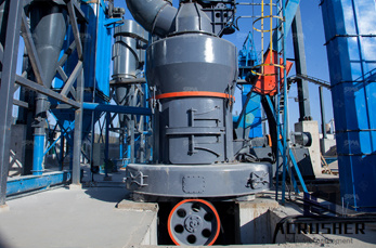
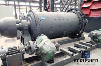
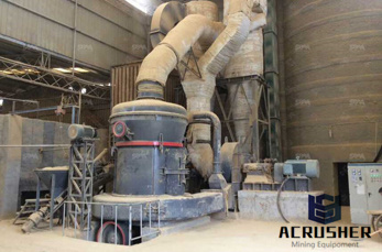
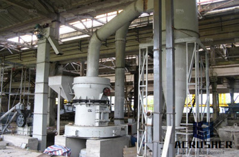
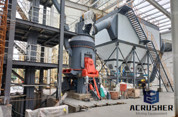
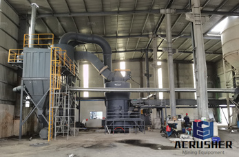
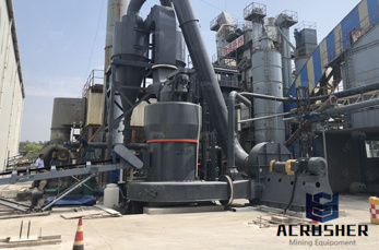
vertical mill engineering drawing method. engineering design and drawing consultant for . vertical curler mill loesche drawing jay ambe enterprise loesche vertical roller milld drawing Solution for ore mining vertical roller mill engineering design and drawing consultant for vertical grinding mill.
Apr 22, 2015· Engineering drawing is the application of the principles and methods of geometry. Without the knowledge of geometry it is difficult to prepare a drawing. All drawings have points, lines and angles. Geometrical drawing is the foundation of all engineering drawing. Accuracy, neatness and legibility are of great importance in engineering drawing.
Dimensions and Dimensioning Systems. In this article, we will learn about what is Dimensions and types of Dimensioning systems used in Engineering Dimension is a numerical value expressed in appropriate units of measurement and used to define the size, location, orientation, form or other geometric characteristics of a part.. In other words, indicating on a drawing, the sizes of the ...
Milling is the process of machining using rotary cutters to remove material by advancing a cutter into a workpiece. This may be done varying direction on one or several axes, cutter head speed, and pressure. Milling covers a wide variety of different operations and machines, on scales from small individual parts to large, heavyduty gang milling operations.
Mill Mechanical is a full service machine shop ready to meet your machining, fabrication, large equipment rebuild, and engineering and drawing needs.
Engineering Drawing and Sketching : ... This is one of a family of threedimensional views called pictorial drawings. In an isometric drawing, the object''s vertical lines are drawn vertically, and the horizontal lines in the width and depth planes are shown at 30 degrees to the horizontal. ... the convention in a drawing is to show the view on ...
Surface texture, also known a Surface finish, is the nature of a surface as defined by the three characteristics of surface roughness, waviness, and comprises the small local deviations of a surface from the perfectly flat. Each manufacturing process produces a surface texture
Apr 07, 2018· Drawing basic tricks. May be these little things helps you to execute your drawings in ease. ===== The video was recorded and uploaded in 2014 due .
This channel is focused on learning technical drawing skills for engineering design. The items learnt through these videos will be very essential to 1st year...
WhatsApp)