
hydraulic schematic diagrams of mill plant manufacturer Grasping strong production capability, advanced research strength and excellent service, Shanghai hydraulic schematic diagrams of mill plant supplier create the value and bring values to all of customers.
 WhatsApp)
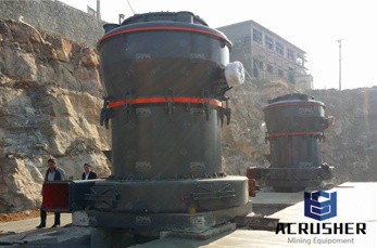
wind mill block diagram Block Diagram Of Cement Mill Pdf Customer Casewind mill block diagram ; cement plant, ball mill, vertical mill mill 3 capacity sand cement block maker in south africa block diagram of cement Controlled Variable Speed Wind Turbine Generation Physical diagram of the system 2 operation is a very simple case that can be used as a baseline.
Although a hydro electric power station simply involves the conversion of hydraulic energy into electrical energy, yet it embraces many arrangements for proper working and schematic diagram of hydro electric plant is shown in the figure dam is constructed across a river or lake and water from the catchment area collects at the back of the dam to form a ...
The previous articles in this series introduced fluids circuit elements and presented example hydraulic schematics. This article describes two example pneumatic schematic diagrams: winder lowering cradle safety pins and winder belted threader operation.
Most of our customers are choosing the correct spool type as they expected, but for few clients, it is better to know more than about hydraulic spool valve diagram before purchasing hydraulic directional valves. –

Circuit Diagram Of A Regular Hydraulic Plant. 201662recommend regular use of our sos fluid analysis servicestypical metaltometal clearances in hydraulic systems are as a result, inplant process reviews and employee education are ongoing efforts.
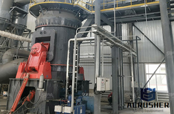
Crossrail block diagram of portal / gantry milling ma .. The pressure can be maintained in the circuit. Get Price; Hydraulic system vertical roller mill operation SlideShare. Mar 25, 2015 . The hydraulic system of vertical mill is an important system, the main function of the hydraulic system is to break the grinding roller, which is. Get Price
How to Wire DC Hydraulic Power Pack Unit? Here are some Details of hydraulic pump electric diagram,12vdc hydraulic power unit and 24vdc Hydraulic Power Pack hydraulic circuit diagram and electrical diagram. And more, A wireless remote connect wire drawing also show below for single acting Hydraulic Power Wireless Remote can be with a quick connector,can be changed with our .
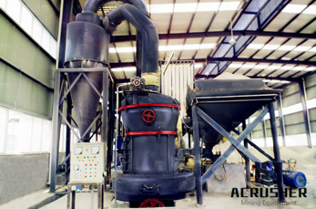
Get Price + hydraulic schematic diagrams of mill plant . hydraulic schematic diagrams of mill plant plant barytes crusher cement mill mills. hydraulic circuit diagram for vertical for dry ball milling circuits . Get Price + Related. Robust Model Predictive control of Cement Mill circuits.
components of single line diagram of cement plant pdf. THIS PAGE INTENTIONALLY LEFT BLANK, This reference . Electrical substation Wikipedia components of single line diagram of cement plant pdf,smaller generating plants were converted to, of transmission lines or other components to and, layout is the preparation of a oneline diagram, .Concrete Batch Plant Operator Study Guide ...

Note: Schematic and product recommendations are intended as a general guide only. Products listed are the product series names. Please refer to equipment builder manual for final lubrication recommendations or consult your Mobil™ Industrial Lubricants team for additional products.
Eaton''s unwavering dedication to leadership in mobile and industrial applications has made Eaton one of the world''s preferred suppliers of hydraulic systems, parts, controls and engineered solutions.
Portland Cement Manufacturing Process Description17 Portland cement is a fine powder, gray or white in color, that consists of a mixture of hydraulic cement materials comprising primarily calcium silicates, aluminates and aluminoferrites. More than 30 raw materials are known to be used in the manufacture of portland cement, and these

If you decide to make one of those widely used piping and instrumentation diagrams, or PID, which is a technical drawing that shows the details of piping and instrumentation of a processing plant, then we recommend you to use ConceptDraw DIAGRAM software as the unique and very useful tool for ...

Apr 24, 2017· How To Read Hydraulic Power Unit Schematics ... We are going to spend a handful of videos looking at different sections of a typical system schematic, starting with the hydraulic power unit (HPU). ...
Oct 21, 2017· Types Of Hydraulic Motors And Their Symbol Used in Hydraulic Circuit Diagram. 4. Hydraulic Cylinder. Hydraulic cylinder is a mechanical hydraulic actuator that converts hydraulic energy or hydraulic pressure into linear displacement. It .
TS 112 Process and Instrumentation Diagrams (PID) SA Water Technical Standard Revision 16 December 2015 Page 3 of 27 For Official Use Only Uncontrolled When Printed Or Downloaded
The following pages go through all standard ISO symbol information as it applies to hydraulic and pneumatic schematics. There are still many plants that modify the standards to suit some individual''s taste. This widespread practice may be confusing to novices. Symbols have been developed to represent most of the available fluid power components.
Training Basic Hydraulics. Table of Contents. Description Pg. Best Power to Weight Ratio 5. Simple Hydraulic System 6. ... Open Center Schematic 31. Closed Center LS Schematic 32. Horse Power Consumption 33. ... Hydraulic Schematic Symbols. 7. Dump Pumps. 8. Hydraulic System Components: Gear Pump. Hydraulic Pump Symbol. 9.
Most of our customers are choosing the correct spool type as they expected, but for few clients, it is better to know more than about hydraulic spool valve diagram before purchasing hydraulic directional valves. –
This part of BS 1553 specifies graphical symbols for use in flow and piping diagrams for process plant. A1. Symbols (or elements of Symbols) for Use in Conjunction with Other Symbols ... Basic and Developed Symbols for Plant and Equipment Heat Transfer Equipment Heat exchanger (basic symbols) ... ball mill Mixing (basic symbol) Kneader ...
Hydraulic Schematics Accurate diagrams of hydraulic circuits are essential to the technician who must repair it. If you don''t understand how the system operates, it is very difficult to diagnose possible hydraulic problems. This looks very complicated. To make it easier to understand, we are going to learn how to look at individual
The top of the reservoir blew off, which shut down the mill for seven days. Hydraulic schematics are usually located inside the machine manufacturer''s manual, which is often kept in a maintenance office or storeroom. When a hydraulic problem occurs, the last thing the maintenance person wants to do is to take 15 or 20 minutes to find the manual.
mill plant equipment schematic mill plant equipment schematic Hydraulic Schematic Diagrams Of Mill Plant Prompt : Caesar is a famous mining equipment manufacturer wellknown both at home and abroad, major in producing stone crushing equipment, mineral separation equipment, limestone grinding equipment, etc. Contact ...
Hydraulic Schematic Symbols Airline Hydraulic''s Main Page Basic Symbols Linntinuous line flow line dashed line pilot, drain envelope long and short .
WhatsApp)