
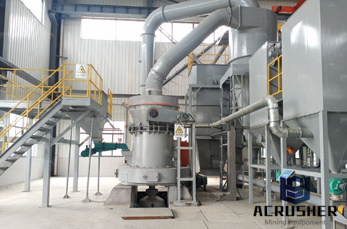
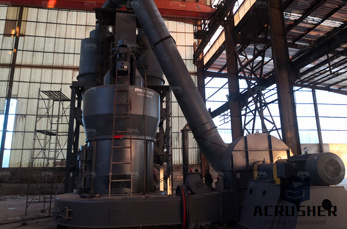
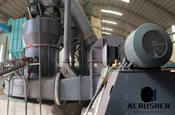
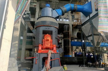
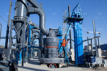
botswana ash plant process flow diagram manufacturer Grasping strong production capability, advanced research strength and excellent service, Shanghai botswana ash plant process flow diagram supplier create the value and bring values to all of customers.
 WhatsApp)
The coal ash disposal ponds are part of an evolving, dynamic industrial process. Each of the sites has at least three or four active ponds of different construction and inactive filled ponds. The ponds are surrounded by a complicated network of hundreds of monitoring and capture wells.
Process Flow Figure 21 US EPA. This is a copy of the Process Flow Diagrams for ExxonMobil Olefins Plant in Baytown Texas Keywords Greenhouse Gas Permit,Prevention of Significant Deterioration,PSD,Air Permitting Process,ExxonMobil Baytown Olefins Plant,Olefins Plant Process Flow Diagrams Created Date 11/14/2012 71315 PM. Get Price []
The second element of coprocessing involves substituting part of the natural raw materials used in the production process with ash residue from the combustion process. Achieving an attractive return on your investments in alternative fuels coprocessing requires comprehensive planning.
"A process flow diagram (PFD) is a diagram commonly used in chemical and process engineering to indicate the general flow of plant processes and equipment The PFD displays the relationship between major equipment of a plant facility and does not show minor details such as piping details and designations Another commonly used term for a PFD is a ...
This system with lime addition can process the many and varied plant waste streams which are traditionally sent to the bottom ash pond. Since the solids contact clarifier has an internal recycle stream which is approximately 10 times the maximum influent flow and hundreds of times more solids than the influent stream, it can absorb the ...
Extraction Of Ultra Pure Silicon From Rice Husk Ash Manufacturing Plant, Detailed Project Report, Profile, Business Plan, Industry Trends, Market Research, Survey, Manufacturing Process, Machinery, Raw Materials, Feasibility Study, Profitability Ratios: Profile Rice husk ash is a unique source of high grade amorphous silica.
Project Report on Sodium Silicate From Silica Sand Soda Ash Project Report on Sodium Silicate From Silica Sand Soda Ash includes Present Market Position and Expected Future Demand, Technology, Manufacturing Process, Investment Opportunity, Plant Economics and Project Financials. Report provides a comprehensive analysis from industry covering detailed reporting and evaluates the .
process: stackgas emissions, bottom ash, and fly ash. Often, bottom ash and fly ash are mixed for waste management purposes, but they may contain different amounts of dioxins and furans. With the exception of a few older wetscrubber units, most municipal solidwaste incineration facilities are able to achieve zero discharge with respect to ...
May 01, 1992· Typical salt analysis. See Table 2. See Fig. 1 for a complete flow diagram of the Solvay process [ 5 ]. Dual process This is a modified Solvay process. It came in commercial use in 1980. Two important prod ucts, soda ash and ammonium chloride are pro duced. This process provides a substantial save in the amount of salt used.
Mar 08, 2016· In a cyclone furnace, where crushed coal is used as a fuel, 70 to 80 percent of the ash is retained as boiler slag and only 20 to 30 percent leaves the furnace as dry ash in the flue gas. (1) A general flow diagram of fly ash production in a drybottom coalfired utility boiler operation is presented in Figure 51. Figure 51.
Jul 01, 2012· Figure 1 outlines the flow diagram from one of the more complex projects. ... process on the diagram is twopass reverse osmosis (RO). ... flow issue at existing coalfired plants comes with ...
process reforms the synthesis gas onsite into a relatively pure hydrogen stream that is then fed to a fuel cell stack. This system utilizes the formation of calcium carbonate to provide heat for reforming while capturing carbon dioxide emissions. Both of these processes result in zero emissions to the atmosphere at the plant .
constitutional phases of MSWI bottom ash, it is therefore similar to the geological materials. A typical scheme for an incineration plant operating on real waste and with energy recovery is given in Fig. 1 Fig1. Flow chart of incineration process The collected material is located in a land site and from here
In incineration process, fly ash is the major reaction surface of dioxin formation, and the metal, metal oxides and metal chlorides on the surface will promote the formation of, fly ash greatly affects the formation paths. It is confirmed that a small proportion of dioxins will be discharged with flue gas and most remained in fly ash, which may be in the range from 106 to 258 ...
The scheme used in physical coal cleaning processes varies among coal cleaning plants but can generally be divided into four basic phases: initial preparation, fine coal processing, coarse coal processing, and final preparation. A process flow diagram for a typical coal cleaning plant is presented in Figure
Direct current is used in the electrodialysis plant, which should have facilities for regulating current in the range of 0 – 185 A and voltage in the range of 0 – 400 V. Flow rates, temperatures, conductivity, pH of process water and product, product inlet pressure, pressure difference between the stacks and current, as well as voltage over ...
Project Report on Sodium Silicate From Silica Sand Soda Ash Project Report on Sodium Silicate From Silica Sand Soda Ash includes Present Market Position and Expected Future Demand, Technology, Manufacturing Process, Investment Opportunity, Plant Economics and Project Financials. Report provides a comprehensive analysis from industry covering detailed reporting and evaluates the .
MAP and DAP are produced utilizing the process illustrated and described below (Click image to view larger): Traditional MAP/DAP Fertilizer (Fertiliser) Granulation Process Flow Diagram The phosphoric acid and ammonia are preneutralized (reacted) in tanks to form a slurry.
Aug 17, 1971· sixdigit SCC for plants with dry process kilns is 305007. ... Both of these materials are produced in portland cement manufacturing plants. A diagram of the process, which encompasses production of both portland and masonry cement, is shown in Figure ... Process flow diagram for portland cement manufacturing.
The process of project management is generally applied to a maintenance shutdown in coal handling plant of thermal power stations. The critical path method (CPM) or sometimes a Gantt charts is used for planning shut down. But it is observed that existing method is not sufficient and foolproof for such type of work. This paper covers a new
Mar 04, 2020· A thermal power generating plant works based on Rankine Cycle. There are mainly three primary inputs given to a thermal power generating plants for producing electricity. These three most essential elements are coal, air, and water. Coal is fuel here because we are going to draw the flow diagram .
Introduction . An Indian consultancy company offers to supply sodium silicate plant on turnkey basis. The conventional process of manufacturing sodium silicate is by the reaction of silica sand with soda ash at about 1,100oC forming water glass, which is crushed dissolved in .
ASH DEC PDay Presentation Pilot Plant Investments and Ownership ASH DEC Operational company invests € 15 M Partner Bank and/or mezzanine capital €1,5 M €1,5 M € 12,0 Mio 50% 50% Dividend Dividend 20% Equity 80% Debt Setup of Operating Companies ASH DEC plants shall be setup and operated by independent project companies. Operators of ...
Nov 19, 2017· Soda ash manufacturing and process flow diagram 1. SODAASH AND BAKING SODA INDUSTRY USAMA PERVAIZ BS CHEMICAL ENGINEER Department of Chemical Engineering, CIIT Lahore 2. PRODUCTION OF SODIUM CARBONATE/BICARBONATE • Uses and History • Raw materials • Process flow diagram • Steps involved in production • 3. Read More
WhatsApp)